cad制作挤出机螺杆平面图的图文操作
时间:2022-10-26 13:37
许多伙伴还不会cad制作挤出机螺杆平面图的操作,接下来小编就分享cad制作挤出机螺杆平面图的操作方法,希望感兴趣的朋友都来共同学习哦。
cad制作挤出机螺杆平面图的图文操作

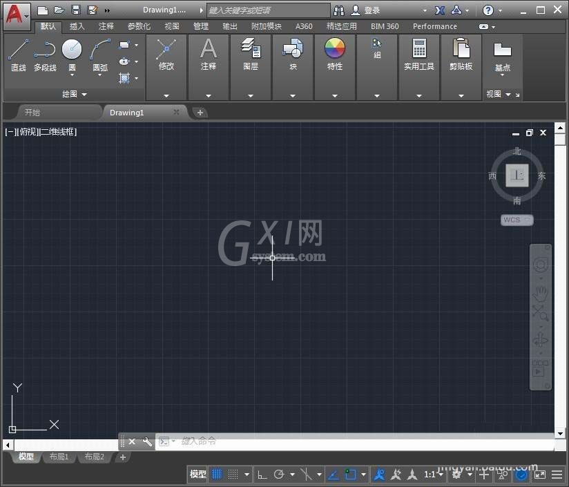
1、打开CAD这款软件,进入CAD的操作界面如图所示:
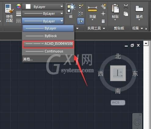
2、在该界面内将线型设置为点画线,如图所示:
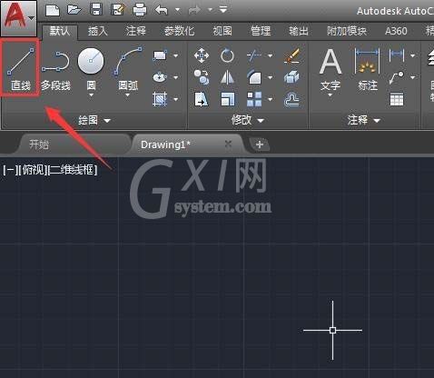
3、设置好线型以后再找到直线命令,如图所示:
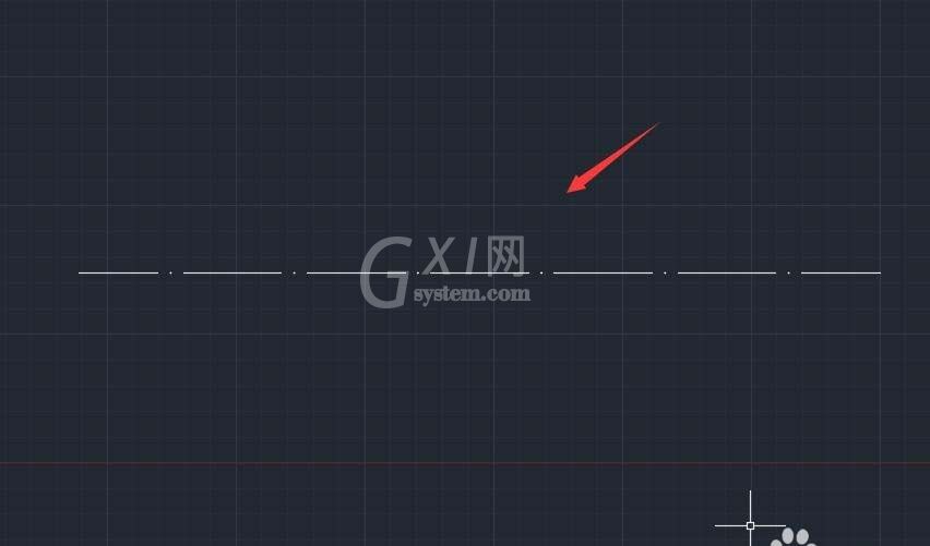
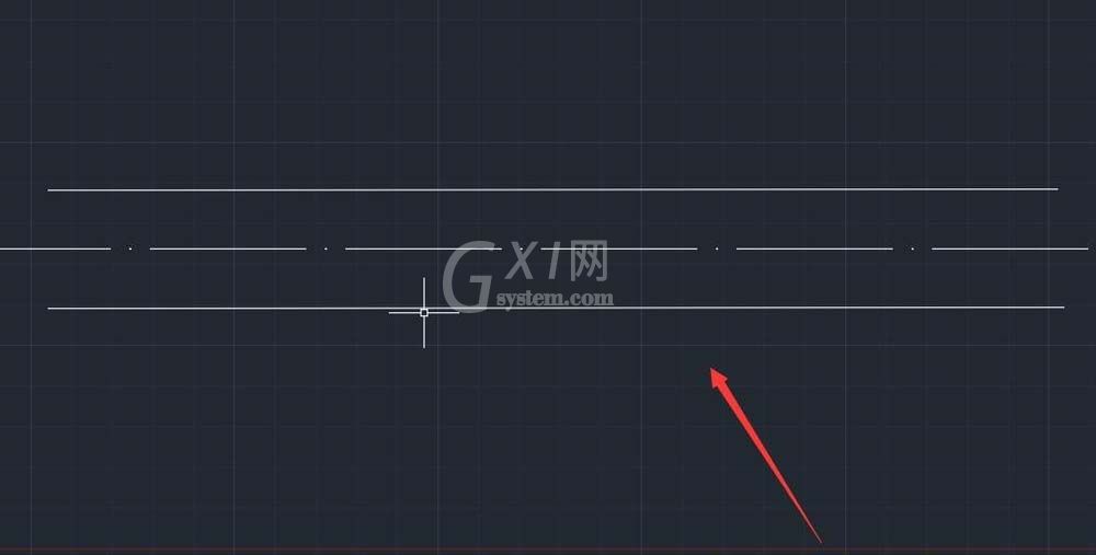
4、使用直线命令画出一条点画线作为中心线,如图所示:
5、再将线型设置为实线,在中心线的上下各画出一条直线,如图所示:
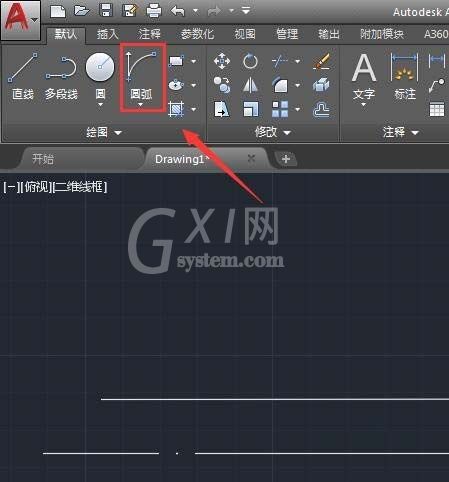
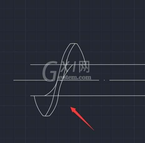
6、再在编区域里找到圆弧命令,如图所示:
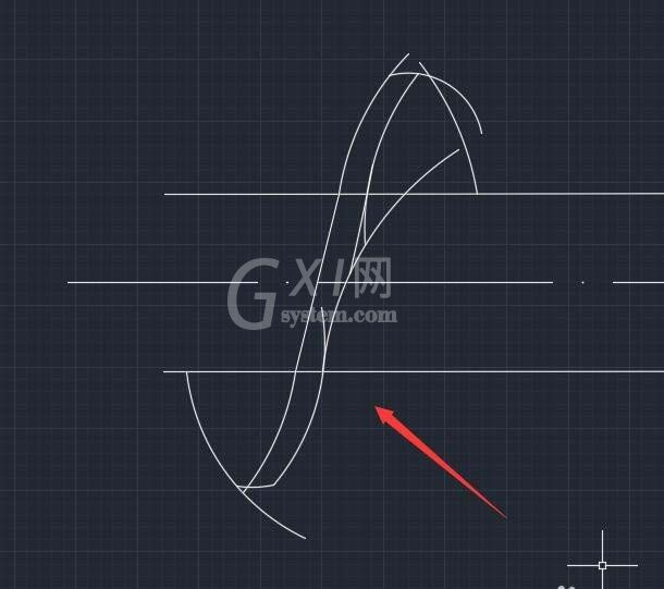
7、使用圆弧命令,在图中画出如图所示圆弧线:
8、绘制好圆弧线以后在上面的工具区里找到修剪命令,如图所示:
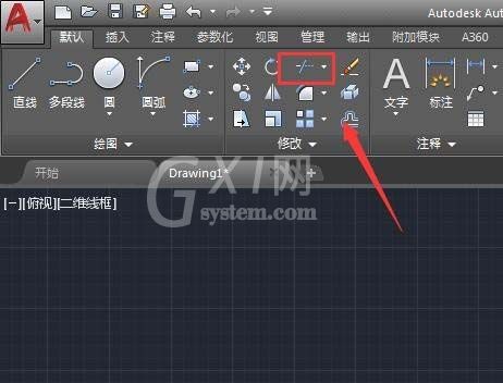
9、点击修剪命令,将多余的线进行删除,如图所示;
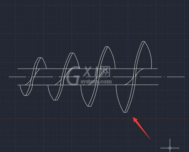
10、再重复执行以上的步骤进行操作,这样我们的挤出机螺杆的图形就画好了,如图所示:
各位小伙伴们,看完上面的精彩内容,都清楚cad制作挤出机螺杆平面图的图文操作了吧!


热门排行
今日推荐


热门手游
-
商场购物模拟器官方版

版本:v1.0.9
大小:46.11MB
日期:2024-12-16
-
滚动方块大冒险免费版

版本:v1.0.5
大小:26.10MB
日期:2024-12-16
-
恋恋奇缘体验服版

版本:v1.0.0
大小:131.33MB
日期:2024-12-16
-
炉石传说官方正版

版本:v1.0
大小:100.52MB
日期:2024-12-16
-
人群大师免费版

版本:v2.15.0
大小:57.68MB
日期:2024-12-16
-
方鸡跳跑单机版

版本:v1
大小:63.49MB
日期:2024-12-16